- Description
- Package contents
- Characteristics
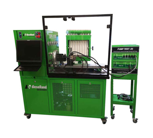
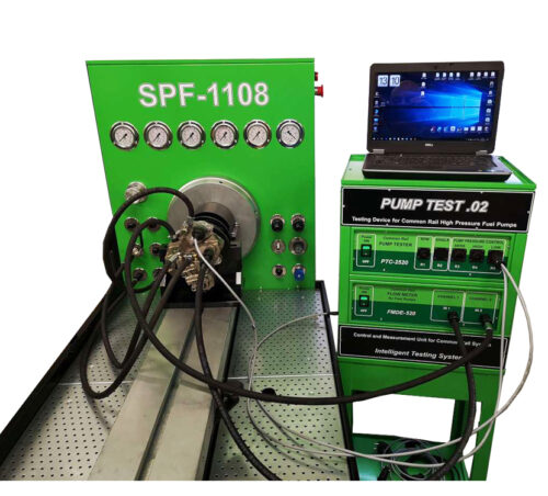
PUMP TEST.02. Common Rail High Pressure Pump Test Equipment
PUMP TEST.02 Common Rail High Pressure Pump Test Equipment
DESCRIPTION AND OPERATION OF THE “FMDE-520” DEVICE
The FMDE 2-channel liquid flow meter is responsible for checking the performance of diesel injection pumps (high pressure fuel pumps) of the Common Rail system.
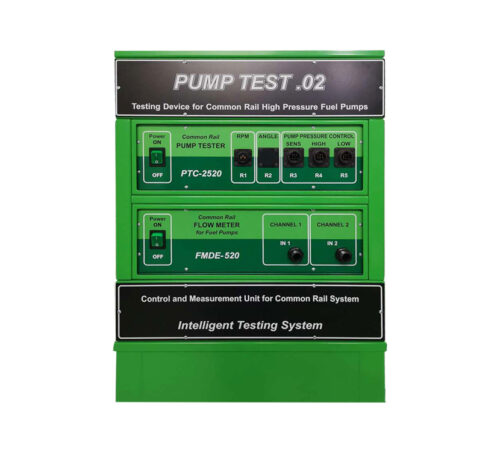
On the front panel there are connections for measuring two flows of test liquid.
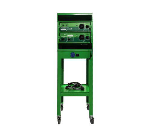
The hose of the first flow (channel) coming from the supply of the high-pressure pump under test through RAIL is connected to the “IN1” fitting.The hose of the second flow (channel) coming from the backflow of the high-pressure pump under test is connected to the “IN2” fitting.The back panel contains:fittings “OUT2” and “OUT1″ for draining the test liquid from the flow meter to the tank.”USB” -port for communication with PC.Ventilation grill.”POWER” mains power switch and “220-240v ~ AC50 / 60Hz” socket for connecting ~ 220V mains power supply. The “MAINS” socket is structurally made in one housing with a fuse.
The FMDE flow meter has two channels for flow measurement:
· Measurement range of sensor No. 1- (6-500 l / h)
· Measurement range of sensor No. 2- (6-500 l / h)
In each channel, temperature sensors are installed behind the flow measurement sensors, which measure the temperature of the liquid (flow).The presence of built-in temperature sensors in the flow meter significantly increases the accuracy of measuring values when checking Common Rail pumps.
ATTENTION! Since solid particles or contaminated enviroment can damage the sensor or affect the measurement, a filter (50 microns) from the delivery must be installed in front of the flow meters (flow sensors)!
The applied flow sensor can withstand the temperature of the measured liquid up to 90C. Do not allow the temperature to rise above this value! Connect the hoses from the injection pump to the meter only through a radiator with forced air cooling of the stand!
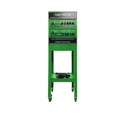
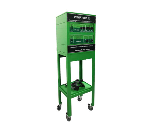
The kit includes:
- 1. Device PTC-2520, which is designed to supply user-programmable control signals for pressure regulators of high-pressure fuel pumps of the Common Rail system to check their operability.
- 2. The device FMDE-520, which is designed to measure the performance of the Common-Rail injection pump through two channels.
- 3. Rack on wheels for easy operation.
- 4. A set of adapter cables.
- 5. Filters for fine liquid purification (2 pcs.)
- 6. Software.
DESCRIPTION AND OPERATION OF THE “CP-TESTER” (PTC-2520)
The device “PTC-2520” allows testing diesel injection pumps of the Common Rail system, giving the necessary user-specified signals to control the injection pump control valves and pressure regulators of the test system.
The panel contains connectors (see from left to right):
SENS connector for pressure sensor
HIGH- connector for connection to the high pressure regulator (DRV)LOW-connector for connection to the low pressure regulator (ZME)
On the rear panel of “PTC-2520” there is:
· “POWER” mains power switch and “220-240v ~ AC50 / 60Hz” socket – for connecting ~ 220V mains power supply. The “MAINS” socket is structurally made in one housing with a fuse.
· “USB” – port.Connector for connecting a safety glass limit switch (for work outside the CR-Test-2P )
· Ventilation grill.
When testing the volumetric performance of CP1 pumps, the amount of fuel that goes to the back drain from the rail is measured through the high pressure regulator (s) at various operating modes (pump speed and pressure).
The principle of testing CP3 pumps is as follows: a pressure accumulator (Rail) with high pressure regulators and a pressure sensor installed on it is used as a load. In these low pressure controlled systems, the pump will have maximum performance when there is no voltage to the regulator, but since the Rail is equipped with a high pressure regulator (s), all fuel will go back to the drain. Further, in the automatic mode, the load pressure is set by the HP high pressure regulator (s), and by closing the LP low pressure regulator with a current of various frequencies, the pump performance is measured (the amount of fuel that goes into the return from the rail through the high pressure regulator (s) in different operating modes) …When testing the CP2 pumps, the same principle is used as the CP3. Rail is used as a load, shutting off the low pressure regulators, the pump capacity is measured. By alternately closing the regulators, the uniformity of the operation of the pump sections is checked.
To test the CP2 pumps, the controller has the ability to use three HP1-HP3 high pressure regulators, since these pumps have a large capacity and the flow area of one regulator is not enough to regulate the pressure in the test system.To carry out the necessary tests of the injection pump, the controller allows you to control the following parameters:· In automatic mode, control the HP1-HP3 high pressure regulator (s) (1-3 pcs), thereby maintaining the pressure in the system from the minimum to the maximum value;· In manual mode, operate the LP1-LP2 low pressure regulator (s) (two regulators are used when testing CP2 cargo pumps).


